
Understanding Network Switches (Motion Applications)
Today, Industrial Automation networks have become faster, smarter, and more robust. The ability of PLCs to simply “talk” to devices by way of distributed control has evolved into much more sophisticated control schemes. For example, today’s modern industrial networks account for reliability and safety in ways never imagined. Plus, there’s a wide variety of network types that users can leverage or implement, depending on their needs. Progress aside, the hardware needed to physically wire/connect the devices of a networked control system together are fundamental. It’s here that we’ll be taking a fresh look at the unassuming role of network switches in modern automation.
We’re going to use EtherNet/IP as our example network for this discussion because it’s the largest and most popular protocol in North America. However, most of the principles we’ll be exploring are applicable to other Ethernet networks (Profinet, EtherCat, Powerlink, etc.), too. Additionally, we’ll be referencing multi-axis motion control applications in this discussion because they’re an exciting application of this technology, however, feel free to imagine whatever device(s) you’re accustomed to networking.
external switch: the traditional approach
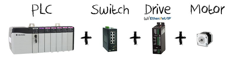
In a typical Ethernet-based motion application the hardware required includes: Ethernet switch, motion controller (Distributed I/O module like Point I/O or AMCI’s ANF1E), a drive and motor. There are also integrated products that combine two or more of these products (integrated drive and control shown) but in all cases a network connection to the PLC is required. This connection is managed through an external switch.
Star Topology
The most common arrangement for the Ethernet communication is a star topology. This is the classic spoke and hub arrangement we think of when we think of an industrial Ethernet network. All data is transmitted through the switch (hub) to the devices on the network (spokes). The external switch manages and controls all functions of the network. It also acts as a repeater for the data flow.
The star topology reduces the impact of a line failure by connecting all of the systems to a central node. When applied to a bus-based network, this central hub re-broadcasts all transmissions received from any peripheral node to all peripheral nodes on the network, sometimes including the originating node. All peripheral nodes may thus communicate with all others by transmitting to, and receiving from, the central node only. The failure of a transmission line linking any peripheral node to the central node will result in the isolation of that peripheral node from all others, but the rest of the systems will be unaffected.
Advantages:
- Devices communicate through an external switch
- Easy to add nodes
- A node failure does not take down the network
Disadvantages:
- Requires more cabling
- Number of nodes is limited by the switch
- Switch is an added cost
- If the switch fails, the entire network is comprimised
Figure 1: Animated Demonstration of Star Topology
embedded switch: an integrated approach
Recent advances in network technology have allowed manufacturers of motion control products to add embedded Ethernet switches into their products. System designers no longer need to include, or can significantly reduce the need for (or the size of) their external Ethernet switch. This greatly reduces hardware and cabling because there is simply less physical product required. (See image below)

With an embedded Ethernet switch, the network design can be either a linear topology or ring topology. Each with their own advantages and disadvantages. With a ring topology there is the benefit of fault tolerant network capability that will be described below.
Linear Topology
A linear network is a collection of devices daisy-chained together. Each device along the network has its own embedded switch. The devices' embedded switch allows the implementation of this topology at the device level. There is no external switch.
Advantages:
- Switch is embedded in each device
- Simplifies installation
- Easy to add a node
- No special configuration software
Disadvantages:
- Any break in the cable disconnects devices down stream of the break
- Troubleshooting can be difficult
Figure 2: Animated Demonstration of Linear Topology
Ring Topology
A ring topology is set up in a circular fashion in which data travels around the ring in one direction and each device on the ring acts as a repeater. Each device incorporates a receiver for the incoming signal and a transmitter to send the data on to the next device in the ring.
Advantages:
- Each device contains a switch
- Resilient to single point failure
- Fast recovery when a fault occurs
Disadvantages:
- More expensive than a linear network
- Must have a method to keep packets from continuously circulating
Figure 3: Animated Demonstration of Ring Topology
Device Level Ring Technology
What is a Device Level Ring (DLR)?
DLR is an ODVA-defined method of managing communication on an Ethernet ring topology.
DLR offers the benefits of both linear & ring topologies: no external switch or special configuration software, easy to add node, simplifies installation, fast recovery, etc., while providing fault protection by converting to a linear topology when a fault occurs. With DLR, you won't deal with the network being compromised (as you do with star topology) and further, devices down stream of the break will continue to operate (unlike with linear topology).
How it works:
One of the nodes is defined as the supervisor and manages the network traffic. The supervisor sends out a message from both ports called a beacon frame. This message monitors the ring's integrity. Data packets are sent out through the primary port only. The secondary port is blocked from sending data. A ring node receives the message. If it is the intended recipient, it consumes the message. Otherwise, it forwards it on. A ring node can also send messages.
What happens when the Ring breaks?
When a cable fails, the beacon frame (seen as "ok" symbol in figure 4 animation) does not reach the secondary port of the supervisor. A link status ("!" failure notification in figure 4) is sent by the ring node where the break occurred and received by the supervisor.
Figure 4: Animated Demonstration of DLR Fault Detection
Packets are then sent through both ports of the supervisor (see figure 5 animation), and continue operation without interruption until the cable repair is made. It acts as a linear topology until the repair is made. The primary port of the supervisor continues to send a beacon frame and when the repair is made, the secondary port receives the beacon frame. Once the repair is made, the supervisor will return to sending the packets through the primary port only, resuming ring topology.
Figure 5: Animated Demonstration of DLR Fault Mode (functioning as Linear Topology)
Taking Advantage of an embedded switch with Integrated motion Products
Having the Ethernet switch built-in to the product opens up the benefits associated with using a Linear or Ring Topology. Integrated PLC-based motion products use the PLC as the central controller for the motion, and combine two or more functions to simplify installation and save time & money.
Integration stepper control products available on the market today include:
- 2-in-1 Drive/Controller
- 3-in-1 Motor/Drive/Controller
The hardware requirements for each of these integrated approaches are outlined in the diagrams below.
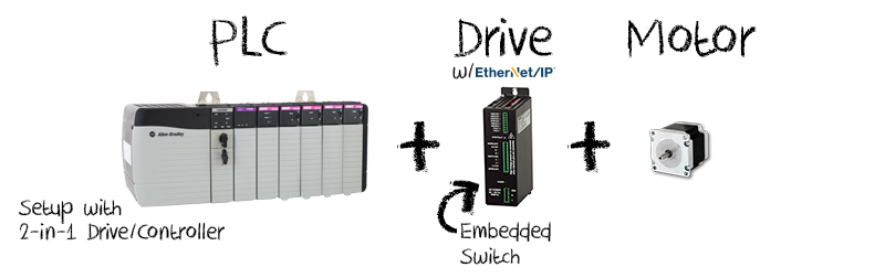
Benefits of a 2-in-1 Drive/Controller include:
Embedded switch, supports DLR, eliminates cabling between the controller & drive, direct communication with the PLC through the network, programs using the PLC's software (nothing new to learn), standard cabling and interface.

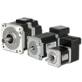
Benefits of a 3-in-1 Motor/Drive/Controller include:
The most efficient method to add sophisticated motion. Embedded switch, supports DLR, compact all-in-one design for complete motion control, replaces cabling between the controller and drive and motor with direct network communication with the PLC, programs using the PLC's software (nothing new to learn), uses standard cabling, available in standard motor sizes, optional encoder and gear boxes are available.
Product Brochure
All of our products in one place - see our entire product offering, learn about our user-friend...
PDF Download